1994-95 BMW 530i/540i Chip Install
Instructions
These new instructions should help
owners of the 530i/540i install any aftermarket Performance Chip into a Bosch
ECU ending in "404" or "484". Almost all of the pictures
below are clickable for a super-sized image.
Take the ECU to your workbench
after you have removed the ECU from your car. Remember to discharge any static
electricity that has built up on your body. For tools, you will need a small
flathead screwdriver, a medium flathead screwdriver, blunt-nose pliers, and a
T20 Torx wrench (we include this last tool).
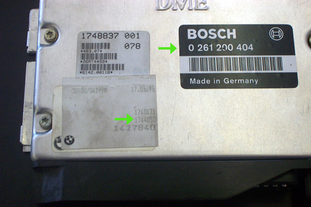
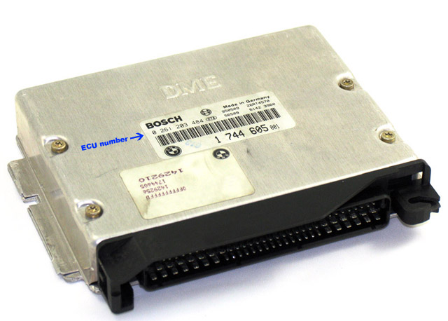
Verify that the ECU number is 0
261 200 404 or 0 261 203 484. On a TMS Performance Chip, the last 3 digits in
the ECU number should match the FIRST three digits on the Performance Chip. On
the "404" ECU there should also be a "1744050" number present on a separate label.
If this number - pictured below next to a green arrow - is not on your ECU, call
Turner Motorsport for instructions on getting the correct chip.
-
Unscrew the four Torx bolts on top of the ECU.
-
Flip the ECU over so the part numbers are facing down. Take one of the
flathead screwdrivers and gently pry the locking tabs holding the ECU cover to
its base. These tabs are very weak and will most likely break off while you are
doing this.
-
Once all of the tabs are bent back, flip the ECU over and pull the cover
from the ECU. You should see something like this:
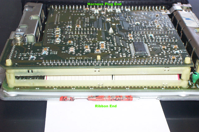
- Notice that
there are two printed circuit boards. On one end is the port where the car's
wiring harness plugged into. The uppermost row of pins is connected right to the
upper circuit board. On the other side is a ribbon connecting one board to the
other. By following the steps below you will be separating the upper board and
folding it over to sit next to the lower board. YOU WILL NOT BE DISCONNECTING
ONE BOARD FROM THE OTHER or cutting the ribbon or any other magic trick. Have
patience and study the ECU carefully and you will successfully install your
Performance Chip.
- Next, insert the small flathead screwdriver into the cone-shaped post
sticking up in the middle of the upper board (see photo above). You will see
slots to insert the screwdriver into. Inside this cone is a rod that locks the
two circuit boards together. With the small flathead screwdriver, push this rod
down. It will come out on the bottom of the ECU. Use the pliers to pull further
but you do not need to pull the rod completely out.
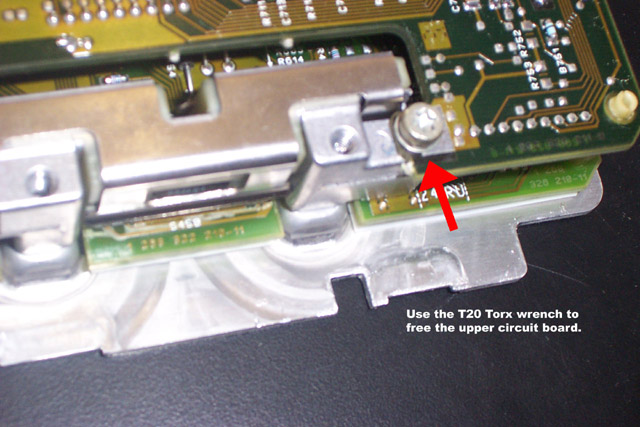
- There is a T20 Torx bolt holding the upper circuit board to the ECU. When
looking at the ribbon from behind this Torx screw is on top on the left.
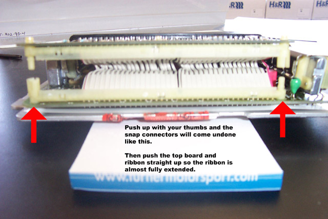
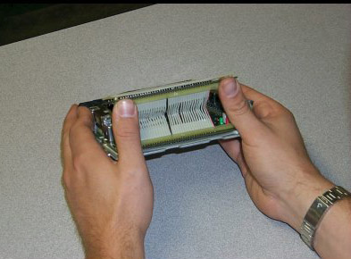
- Hold the ECU in your hands with the wire harness plug facing away from
you and the circuit board facing up. Position your hands so that you can push
the upper circuit board with your thumbs. See the photos below. The snap
connectors on either side of the ribbon will need to come undone. To do this
press firmly on the upper board with your thumbs while holding the ECU stable.
You can do one at a time. MAKE SURE THE TORX SCREW IS REMOVED FROM THE UPPER
BOARD.
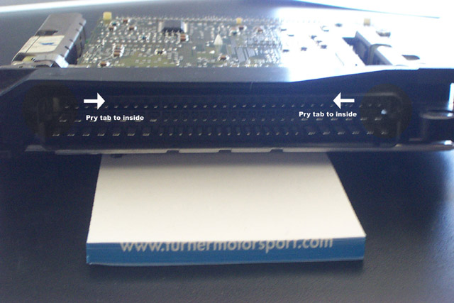
- The final lock holding the upper board in place is on the wire harness
plug end. They are very hard to see. There is a tab on each upper corner of the
plug housing. Look past the very last pin in the upper row and you should be
able to see them. Insert the small flathead screwdriver and pry these tabs
toward the inside of the plug housing. Get these good and loose but do not bend
them too much (they will break). See photo below.
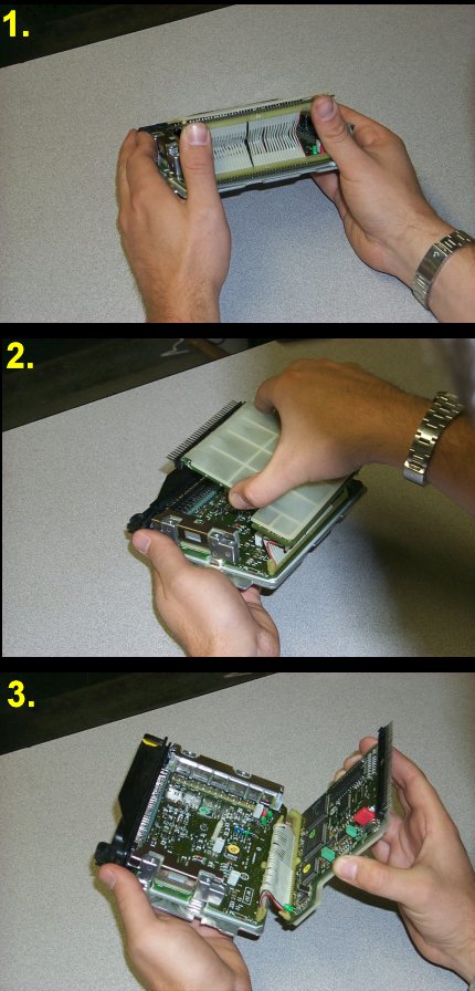
- Now, turn the ECU around so that the plug housing is facing away from
you. Push up on the upper board with your thumbs again until the ribbon is
almost fully extended. There will be a lot of resistance to doing this - both
from the ECU and your own sensibilities - but you have to push the upper board
far up.
-
The upper board is actually attached to the uppermost row of pins in the
wire harness plug. Hold the ECU in your hands, and with the ribbon fully
extended, gently pry the upper board AWAY FROM the wire harness plug housing.
The goal here is to push the uppermost row of pins out of the plug housing.
Remember that this ECU has probably been assembled in this way for ten years. It
will give you some resistance. If all seems lost, try pushing up on the ribbon
some more. The angle of the upper board is crucial to pulling it away from the
plug housing.
- When the upper board comes free, the ECU should look like this:
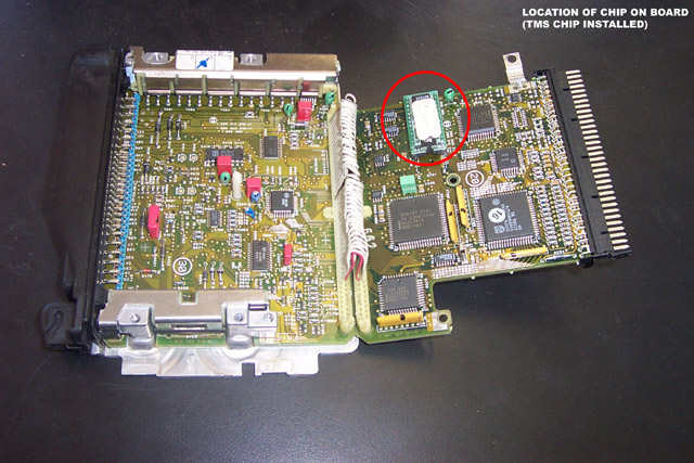
- Note the position of the divot on the stock chip. The Performance Chip
must be oriented in the same direction. The TMS Performance Chip uses an arrow
to denote the divot end. The stock chip is located in a socket (in the red
circle in the picture above). Insert the small flathead screwdriver into one end
of the chip and pry upward. Alternate ends to remove the chip without bending
any of the pins. PRY THE CHIP FROM THE SOCKET - NOT THE SOCKET FROM THE CIRCUIT
BOARD!
- Push the Performance Chip into the socket. Remember that it must be in
the same orientation as the original. Make sure that all of the pins are seated
and all of the socket's holes have a pin in them.
- Fold the circuit board over into the ECU and insert the row of pins into
the housing. Pay particular attention to the cone-shaped post in the middle of
the ECU that must go into the hole on the upper board. When all is lined up and
clear push the circuit board into place. Push down so that the snap connectors
re-connect. Re-install the Torx screw into the upper board. Push the retaining
post back up into the ECU. Slide the cover on and reinstall the four Torx screws
and bend the tabs back into place. If they are broken off and the cover is
loose, you can use tape to seal the edges of the cover.
- Reinstall the ECU into the car and enjoy!


